Mechanical parts
Reconstruct components for which original CAD is unavailable.
QUICKSURFACE / REVERSE ENGINEERING SOFTWARE
The scan is the start. CAD is the next step.
Book a demonstration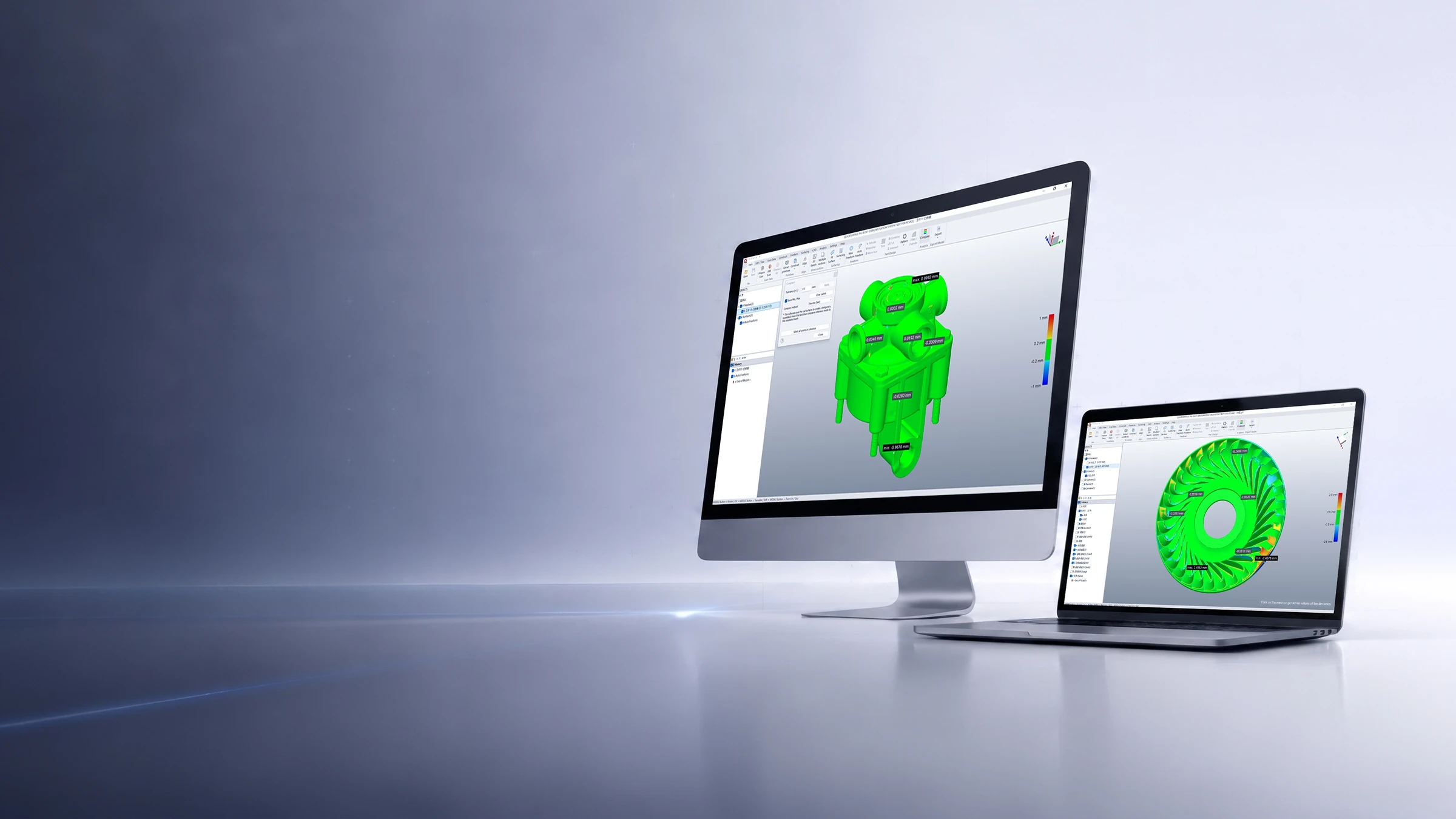
01 / OVERVIEW
Turn measured geometry into a model you can design with. QUICKSURFACE combines scan import, surface reconstruction and deviation control in a standalone reverse engineering environment.
from capture to design
Standalone software.geometry reconstruction
Geometric features and freeform shapes.control while modelling
Comparing the model with the reference scan.02 / 01 / IMPORT
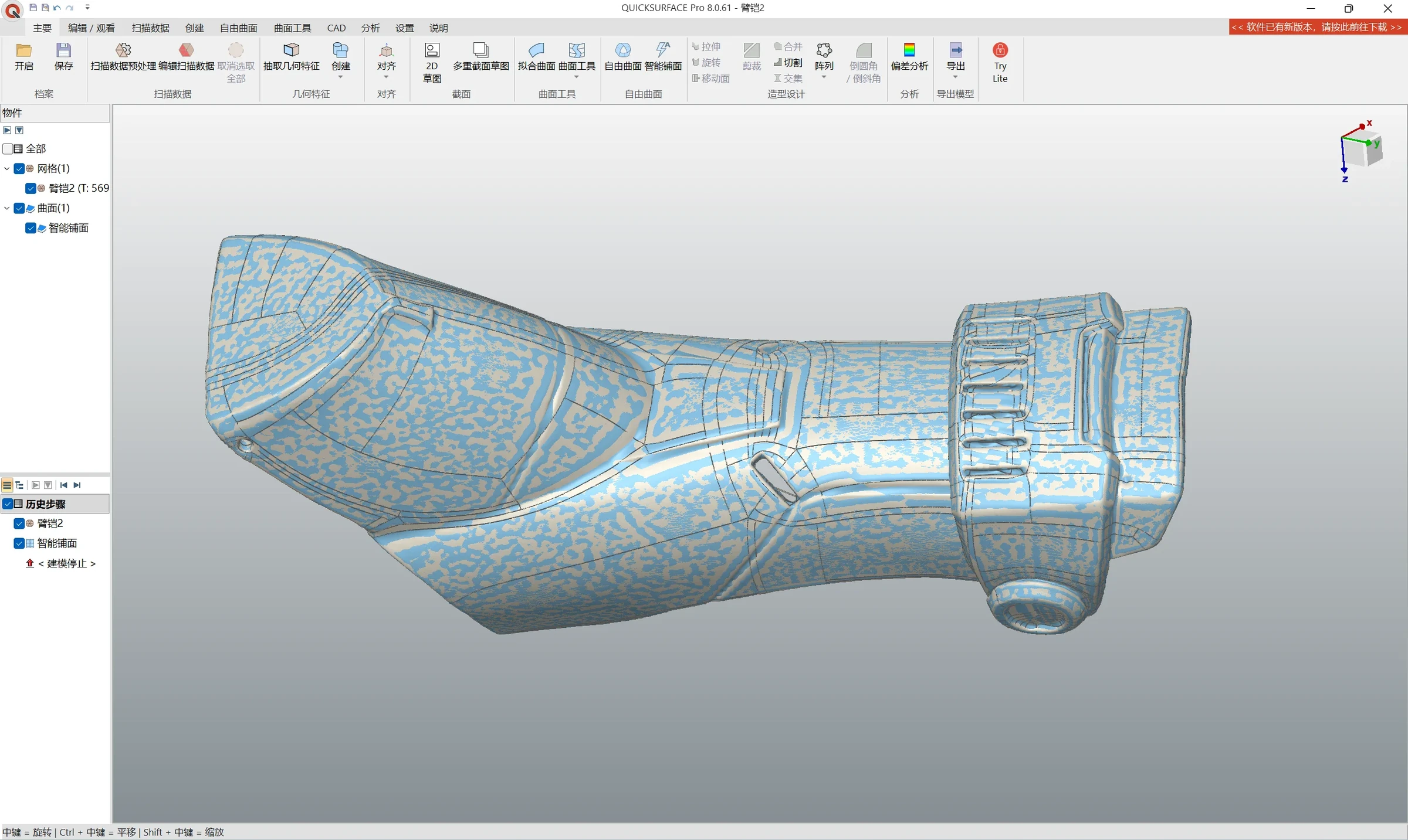
Import an STL, OBJ or PLY mesh or a PTX point cloud. The scan becomes the spatial reference for designing a new CAD model.
03 / 02 / ALIGNMENT
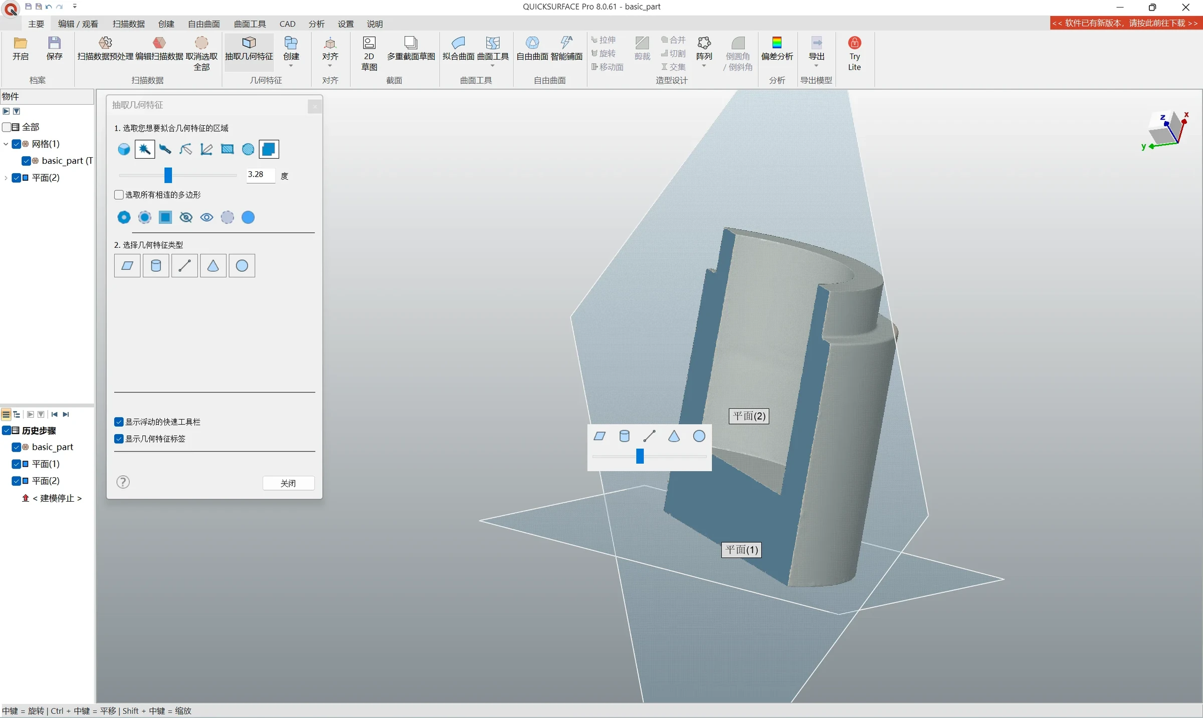
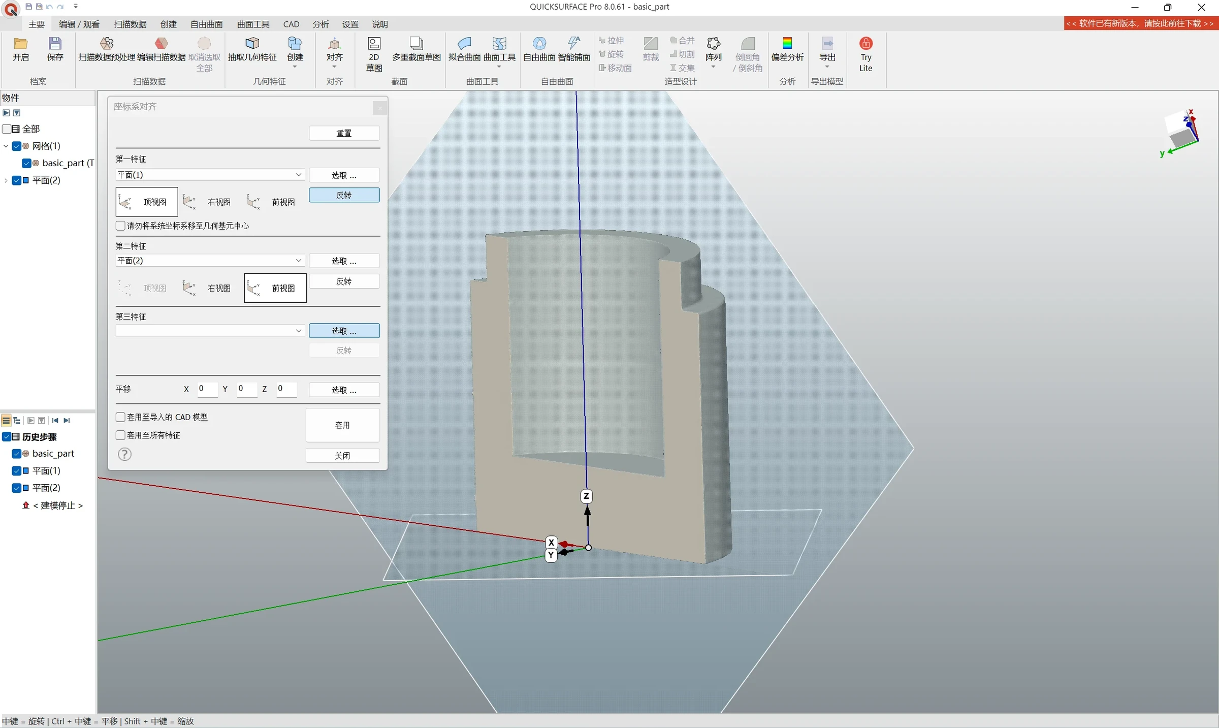
Detect planes, cylinders and other geometric features and define the coordinate system. A correctly oriented scan makes sections and modelling easier.
04 / 03 / SECTIONS
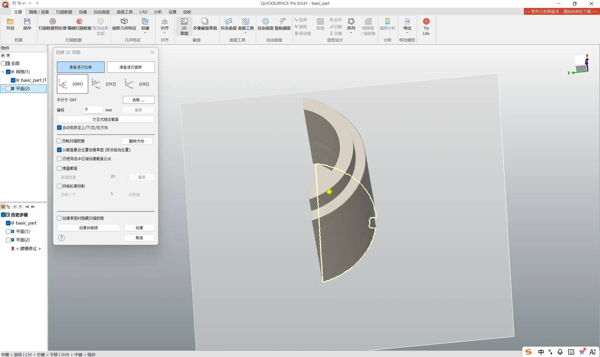
Extract sections of the scanned geometry and use them as sketch references. This prepares the basis for extrusions, revolves and further reconstruction.
05 / 04 / MODELLING
Reconstruct surfaces and solids from the reference data. The parametric workflow lets you go back to design steps and adjust the model.
06 / 05 / FREEFORM
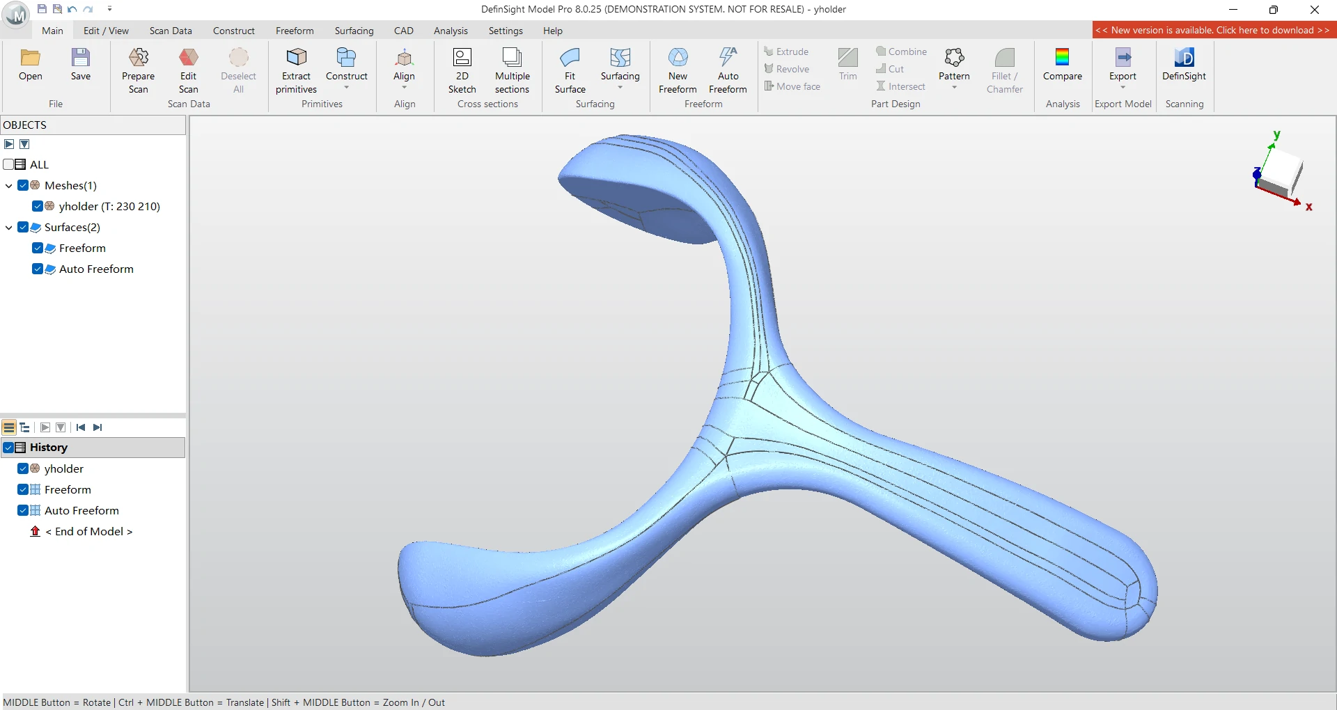
Use surface modelling for shapes that simple cylinders or planes cannot describe. Adapt reconstruction to the product shape and intended use.
07 / 06 / VERIFICATION
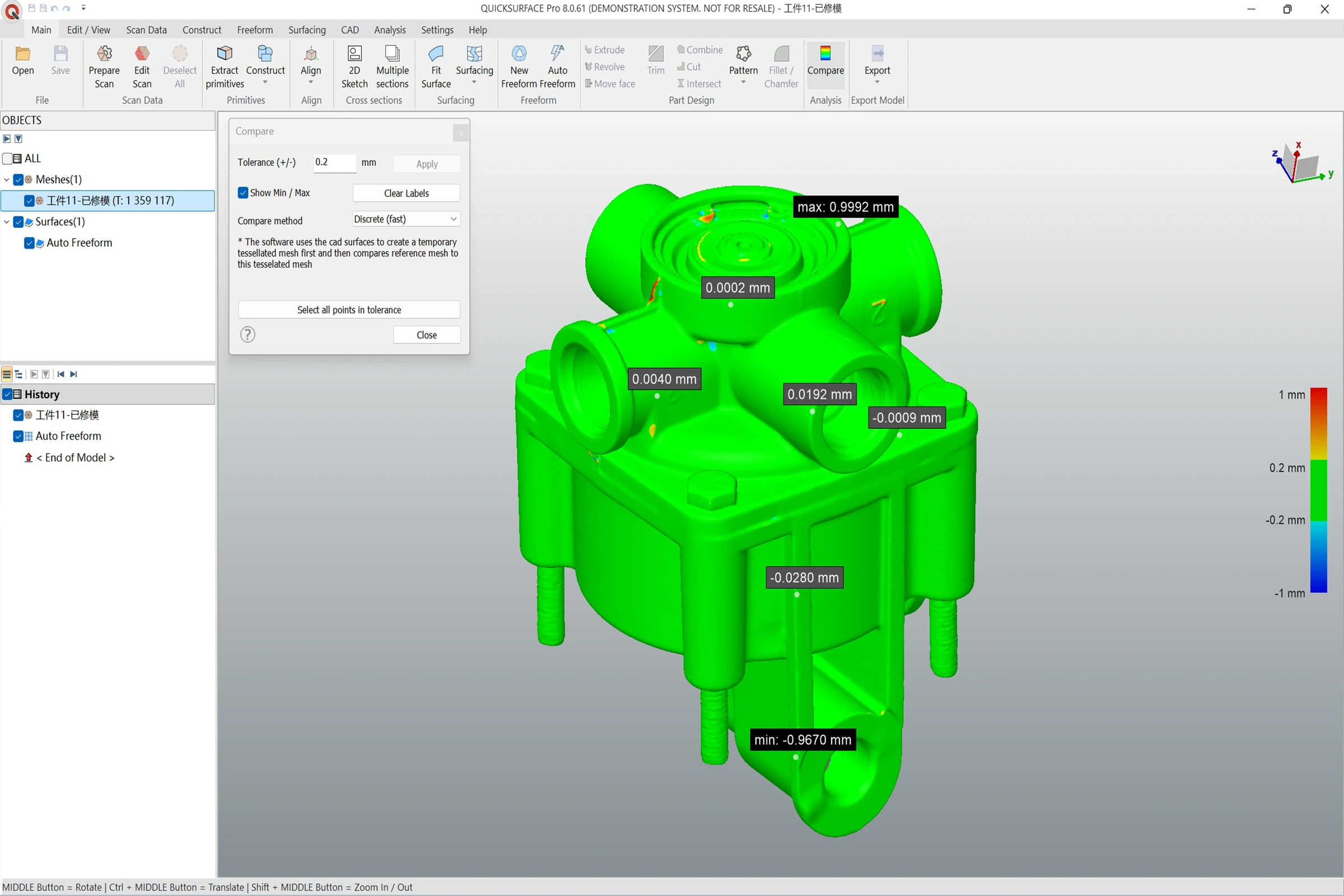
A colour map shows deviations of the reconstructed model from the scan. Follow the fit while modelling and decide where corrections are needed.
MANUFACTURER VIDEO / YOUTUBE
See the process and features in the official video presentation.
Open video on YouTube08 / FROM TASK TO RESULT
Reconstruct components for which original CAD is unavailable.
Use existing geometry as a starting point for changes and new versions.
Prepare surfaces for further industrial design.
09 / TECHNICAL DATA
A selection of key parameters. When choosing, consider object size, required accuracy and working conditions.
Availability of features and formats depends on the chosen edition. When preparing a quote we check the software version you use and your design workflow.
10 / RELATED EQUIPMENT
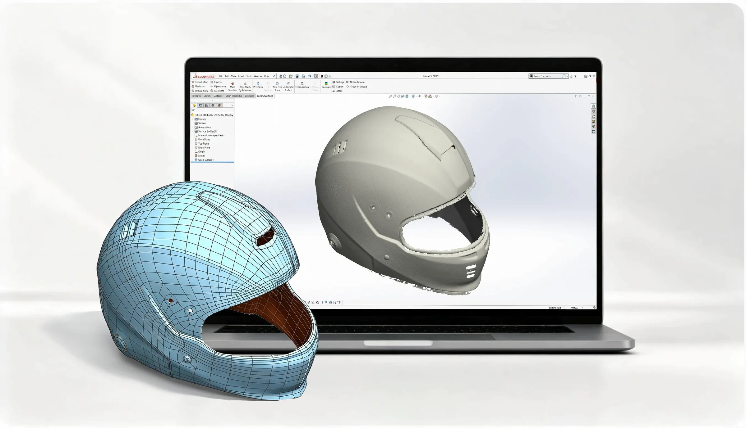
QUICKSURFACE
From scan to CAD in SOLIDWORKS.
Explore the product ↗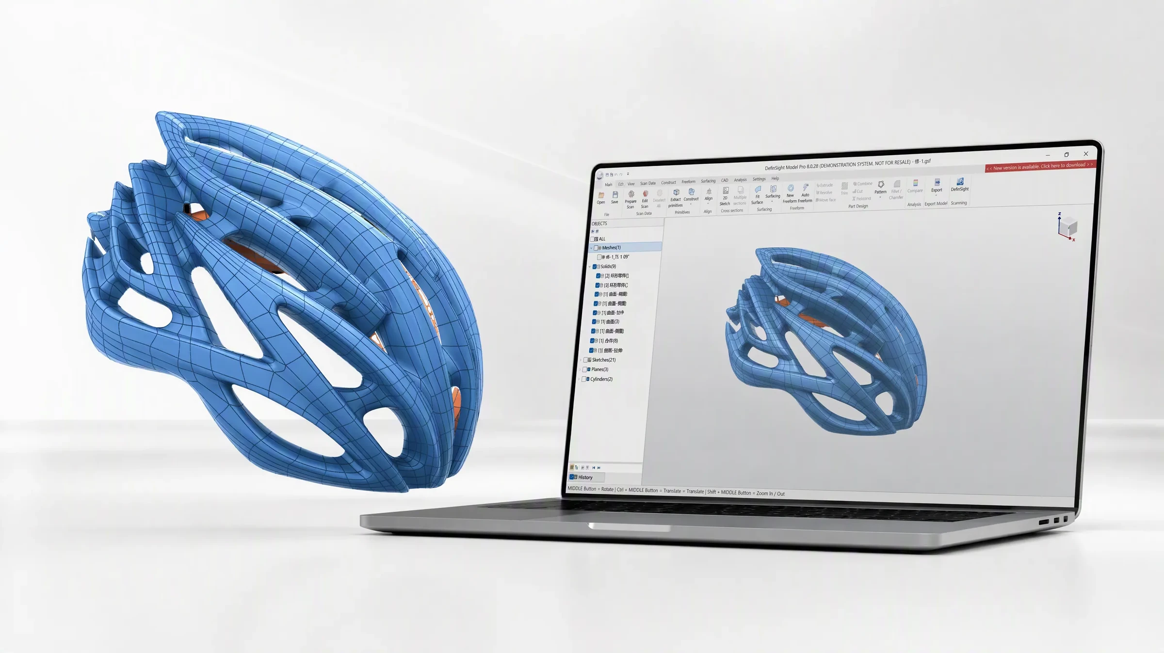
SCANOLOGY
Connect measurement with your next design.
Explore the product ↗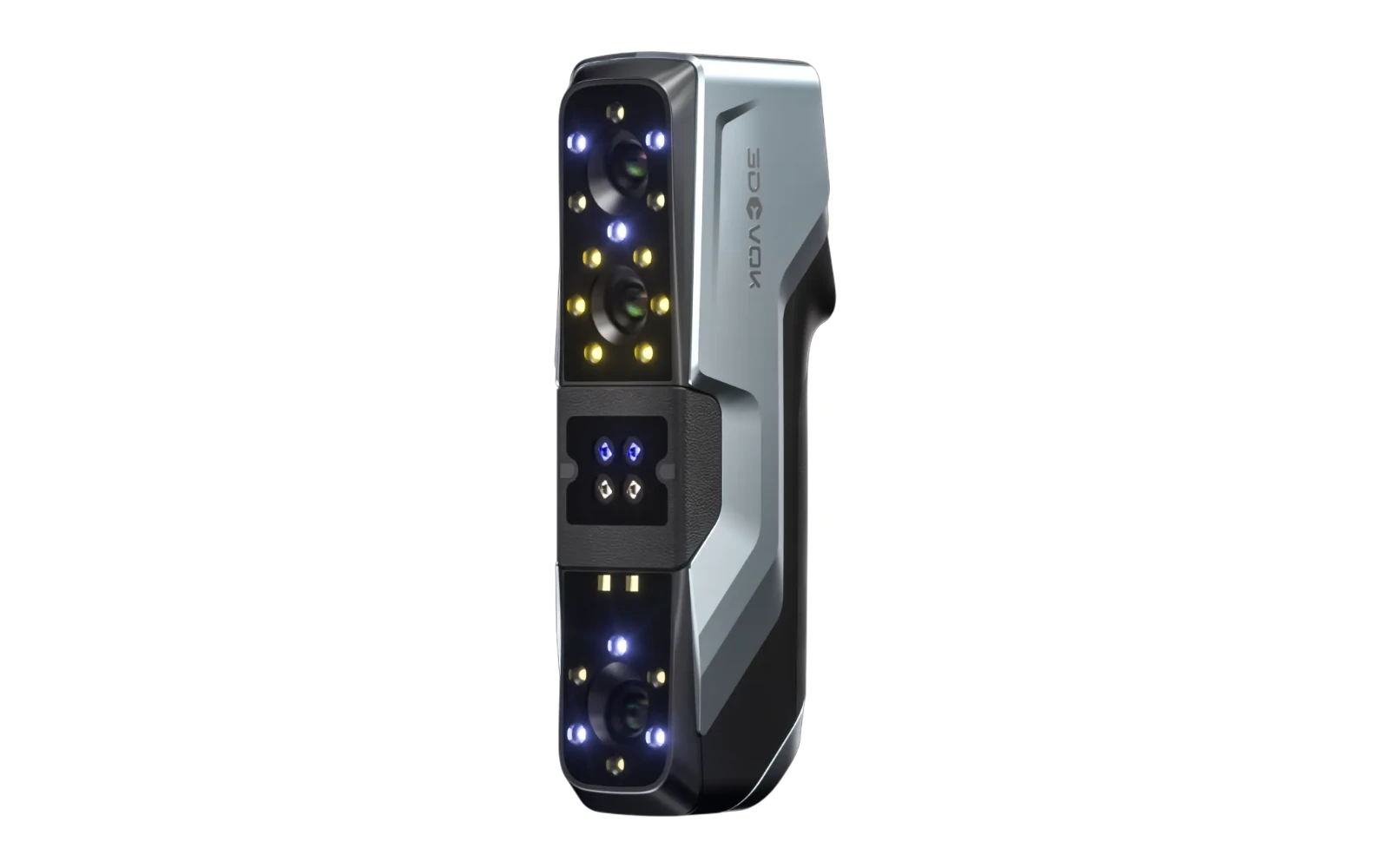
3DeVOK
Three capture modes. More options for your object.
Explore the product ↗3D ING / TALK ABOUT YOUR PROJECT
What do you want to scan and what result do you need?
Describe the object, its size, material and the intended use of the data. Together we can clarify the basis for choosing equipment.