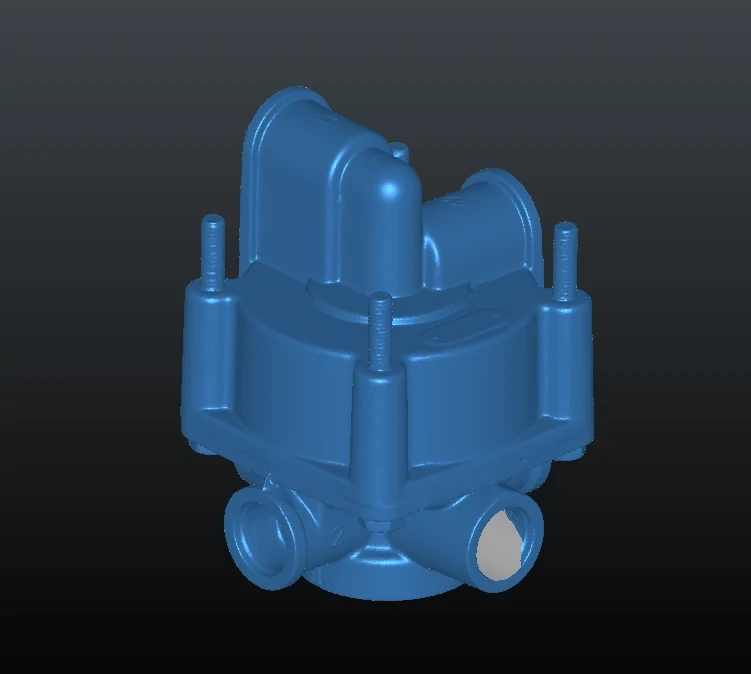
02 / FROM CAPTURE TO MESH
Usable 3D data first.
Scanning the part and collecting data is followed by cleaning, alignment and preparation of the mesh model. We check the capture is complete where it matters for further design.
SOLUTIONS / REVERSE ENGINEERING
Reverse engineering links capturing an existing object, processing the data and reconstructing geometry for further development.
Discuss a solution Explore the workflow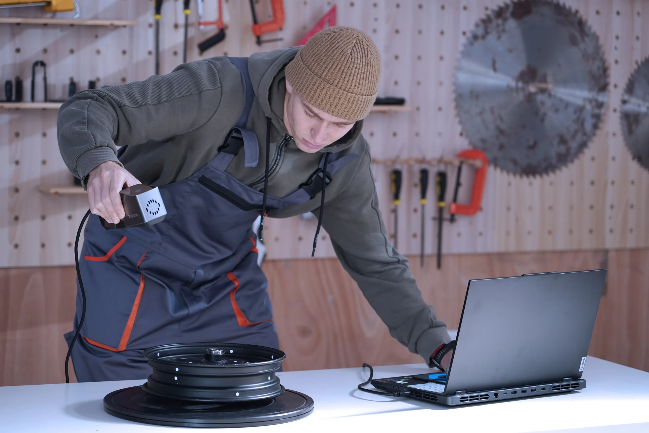
01 / REPLACEMENT PARTS
Capturing older or undocumented components creates a basis for reconstruction. The scan preserves the existing shape; design work defines the dimensions and features of the new model.
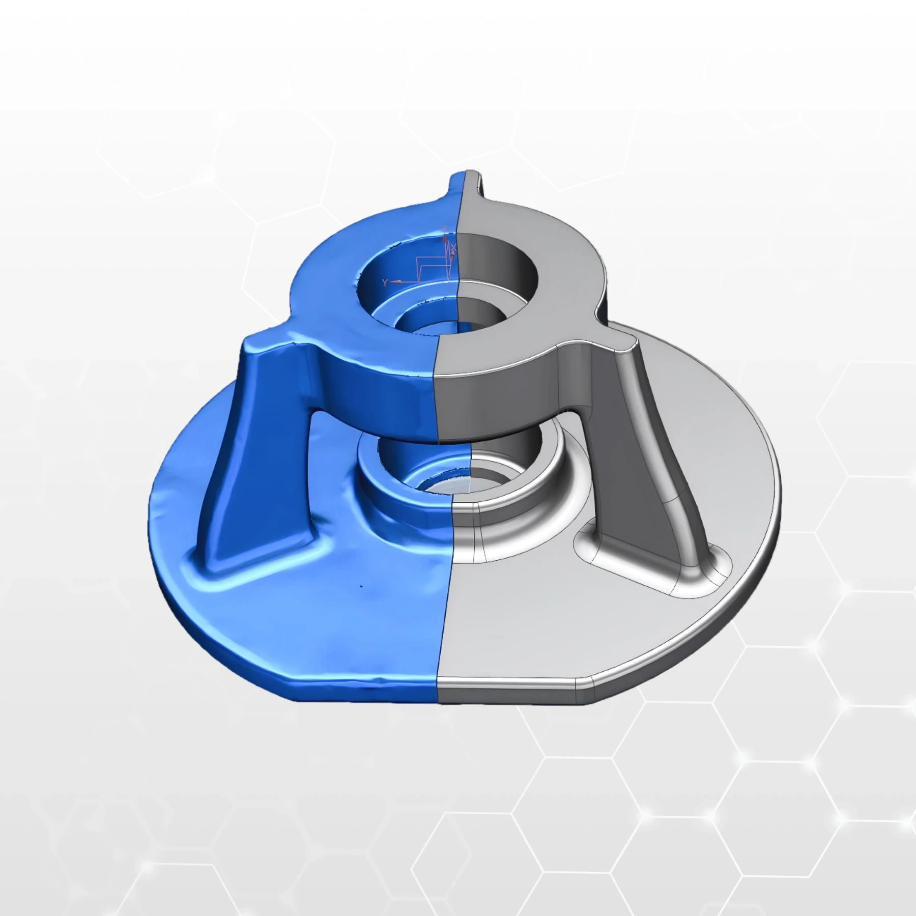
FROM OBJECT TO USABLE DATA
02 / FROM CAPTURE TO MESH
Scanning the part and collecting data is followed by cleaning, alignment and preparation of the mesh model. We check the capture is complete where it matters for further design.
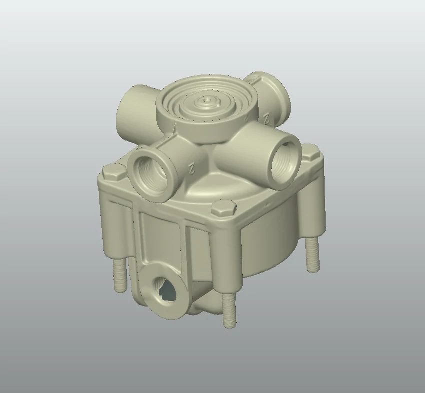
03 / CAD RECONSTRUCTION
The mesh is the starting point for rebuilding surfaces, holes and other geometric features in CAD. STL, OBJ and PLY are formats for further processing; a mesh export by itself is not a parametric CAD model.
04 / DEVELOPMENT AND VERIFICATION
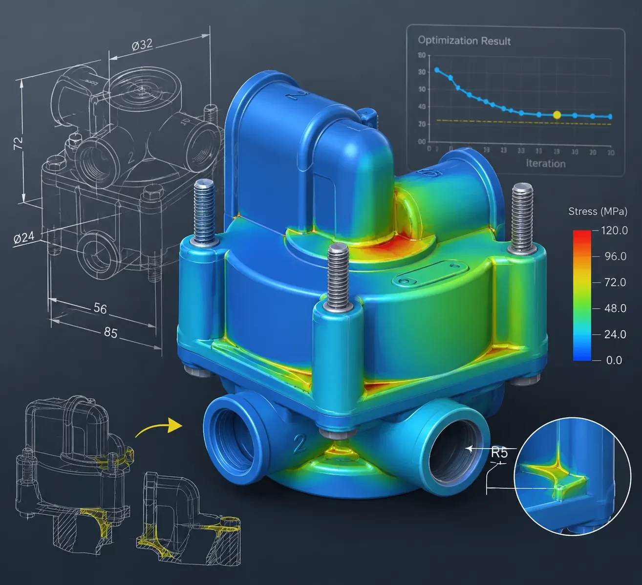
Change dimensions, shape or functional elements and check the reconstructed geometry against the original part. This creates a basis for prototyping or the next design step.
EXAMPLE TASKS
Capturing older or undocumented components for reconstruction and further design work.
Capturing existing surfaces to design mating parts and modifications.
Comparing reconstructed geometry with the original and preparing a basis for prototyping.
WORKFLOW / BASIS FOR CHOICE
Requirements first, then equipment. Possible starting points are MT Gen2, MT and MQ with suitable software. The final choice depends on the specific task.
Enquiry checklistScanning the part and collecting 3D data.
Cleaning, alignment and mesh preparation.
Rebuilding surfaces and design features in CAD.
Changes to dimensions, shapes and functional elements.
Comparison with the part and validation for the intended use.
EXPLORE RELATED EQUIPMENT
3DeVOK
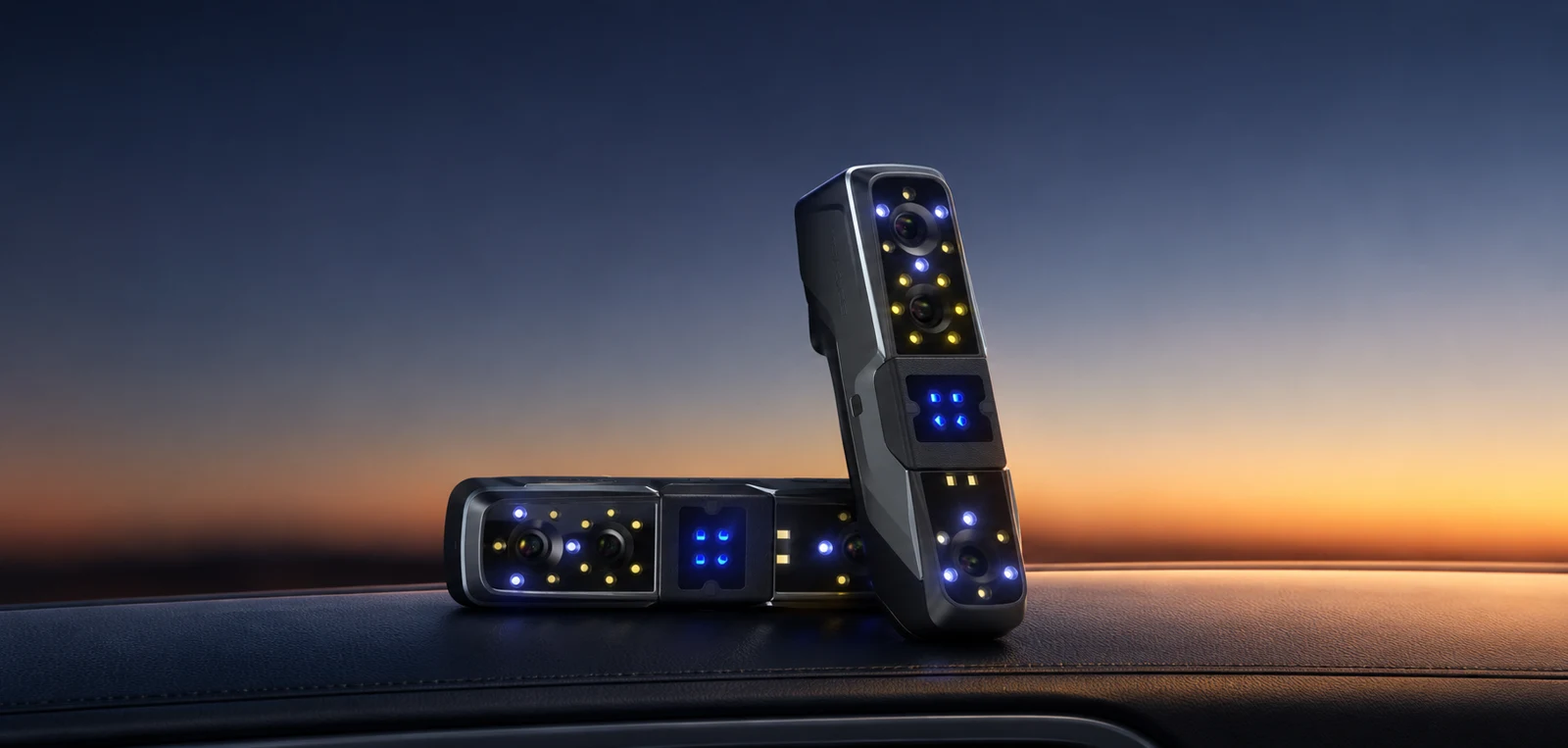
Four light modes. Details that count.
Explore the product ↗3DeVOK
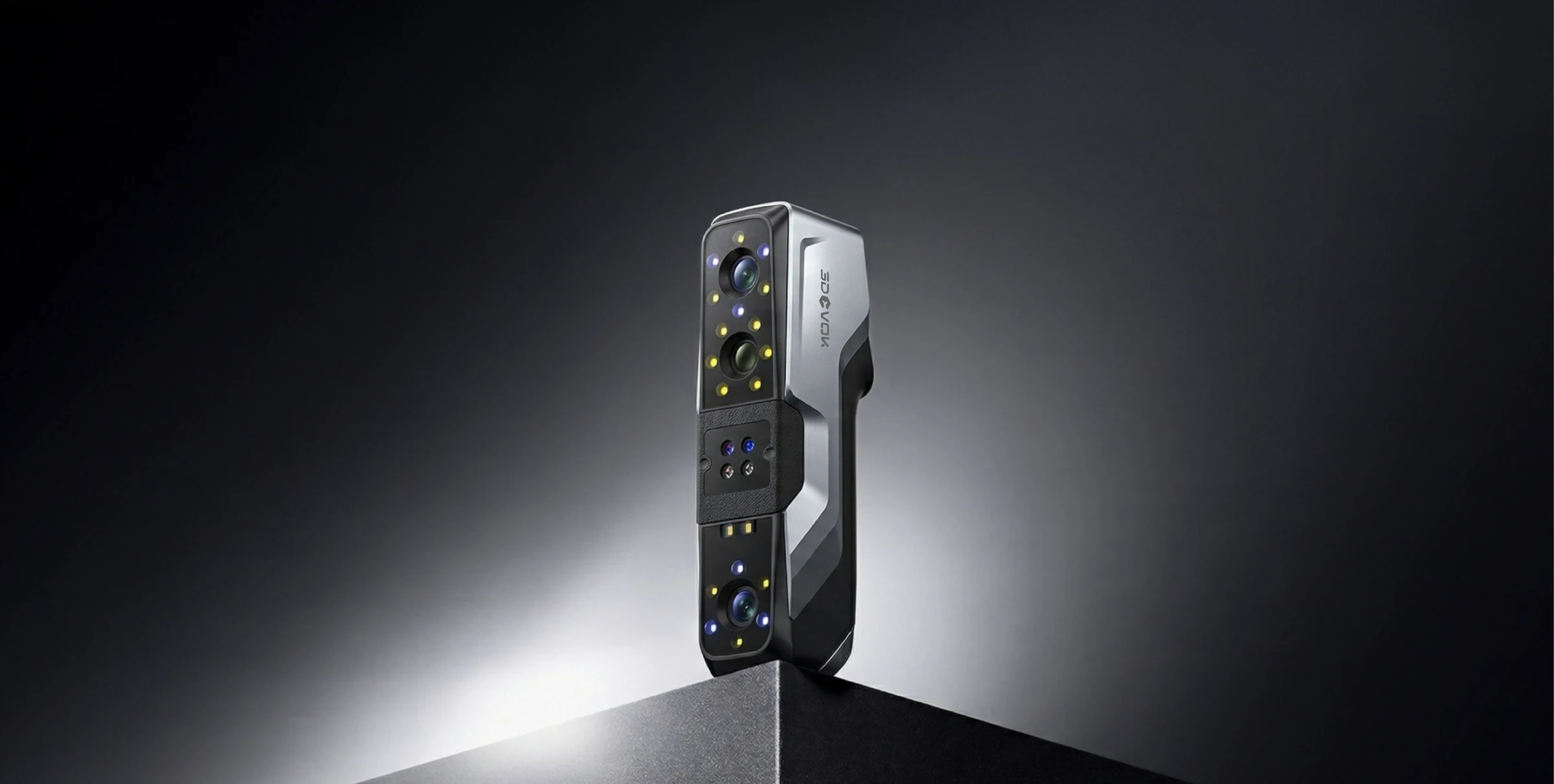
Three capture modes. More options for your object.
Explore the product ↗3DeVOK
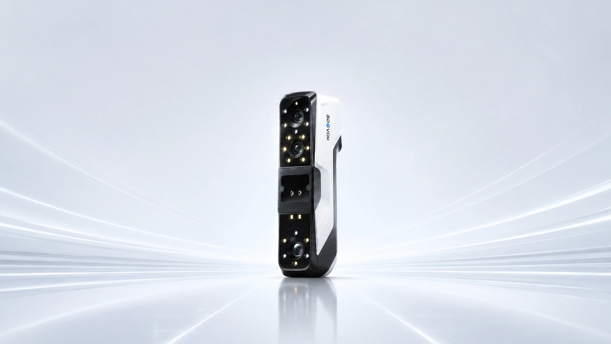
Shape and colour. In one workflow.
Explore the product ↗3D ING / TALK ABOUT YOUR PROJECT
WHAT TO INCLUDE IN YOUR ENQUIRY
Include the part's dimensions, material, smallest relevant features, required tolerance, purpose of the final model and the desired output format.
What do you want to scan and what result do you need?
Describe the object, its size, material and the intended use of the data. Together we can clarify the basis for choosing equipment.