3D-ING Scanning

SOLUTIONS / QUALITY CONTROL

Check the shape. Understand deviations.

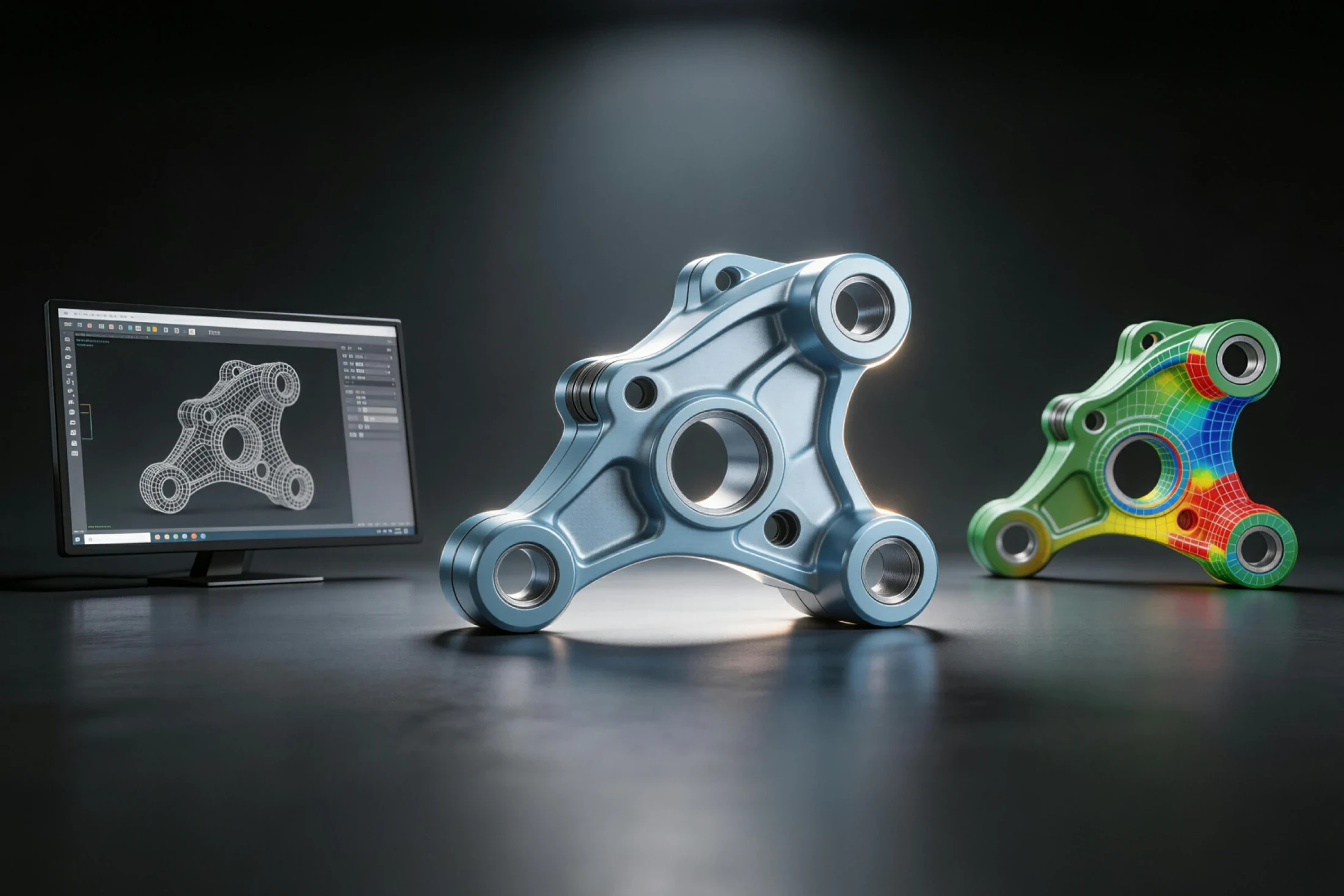
3D scanning captures the product surface for comparison with a reference model. A colour deviation map helps reveal differences that individual point measurements do not fully show.

Discuss a solution Explore the workflow
Machine part, digital model and colour deviation map compared
Quality control / in use3DeVOK manufacturer material.

01 / SURFACE CAPTURE

Understand the complete geometry of the part.

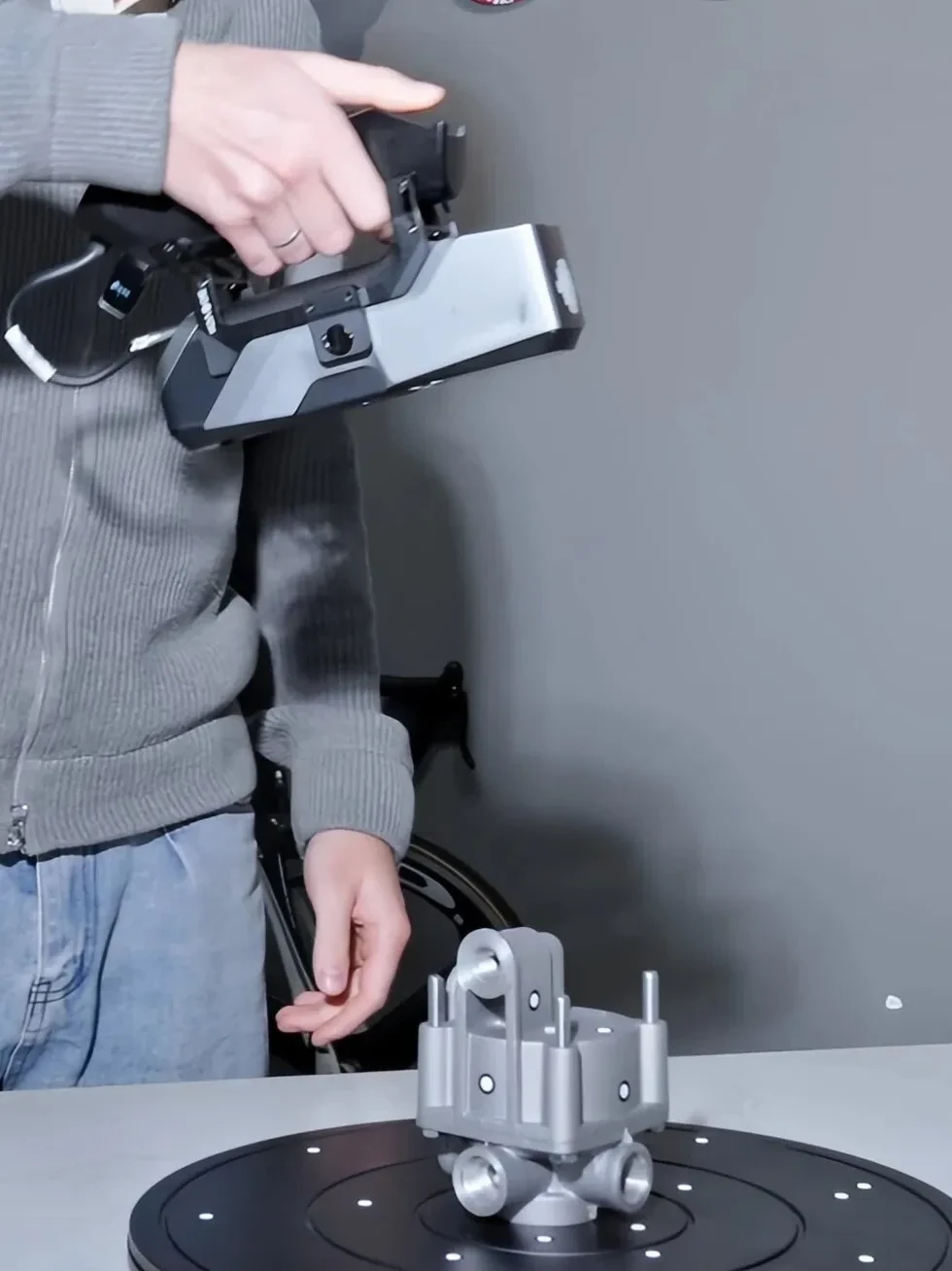
3D scanning captures the product surface for comparison with a reference model. Before measuring, we define tolerances, reference elements and the features to be checked.

Handheld capture of a mechanical assembly
Handheld capture of a mechanical assembly.

FROM OBJECT TO USABLE DATA

From data to clear deviations.

Full workflow
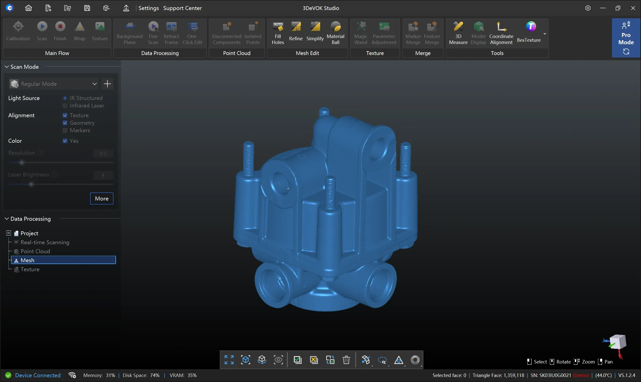
Mesh model of a mechanical assembly in software
Mesh model of a mechanical assembly in software.

02 / DATA PREPARATION

Prepare the model for measurement analysis.

We align the captured data and prepare it for analysis. Processing must preserve the geometry being evaluated; the preparation method and choice of metrology software follow the task requirements.
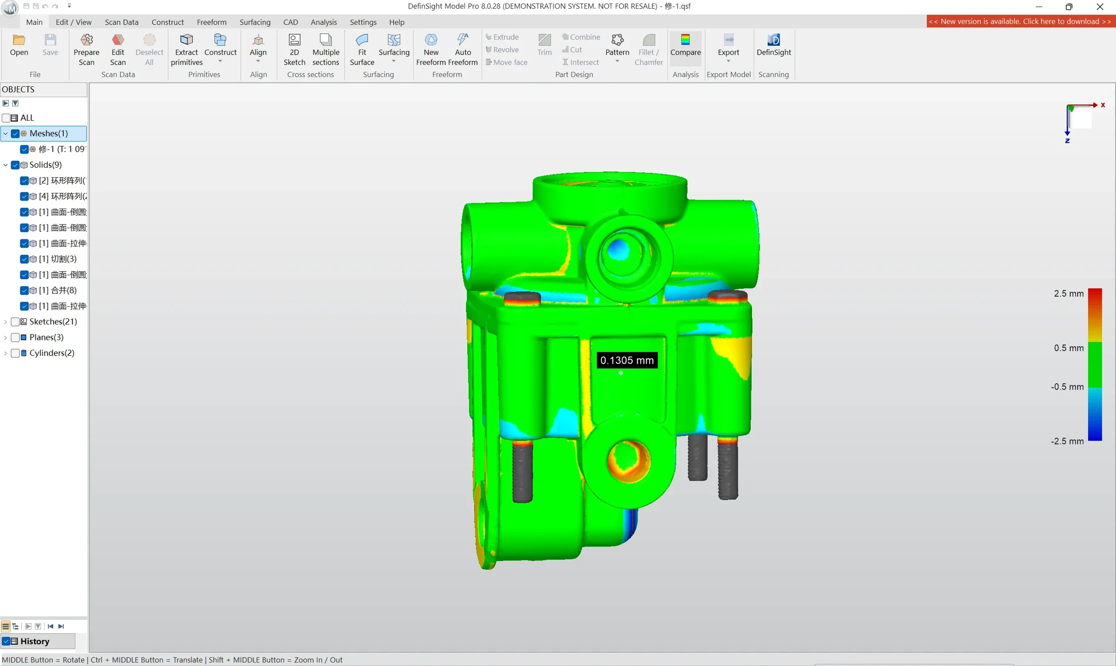
Colour deviation map of a mechanical assembly
Colour deviation map of a mechanical assembly.

03 / DEVIATIONS FROM CAD

See where the shape differs.

A colour deviation map helps reveal differences that individual point measurements do not fully show. The comparison supports inspection of shape, wear and deformation on sheet metal, tools and components.

04 / DOCUMENTATION

Results for quality review.

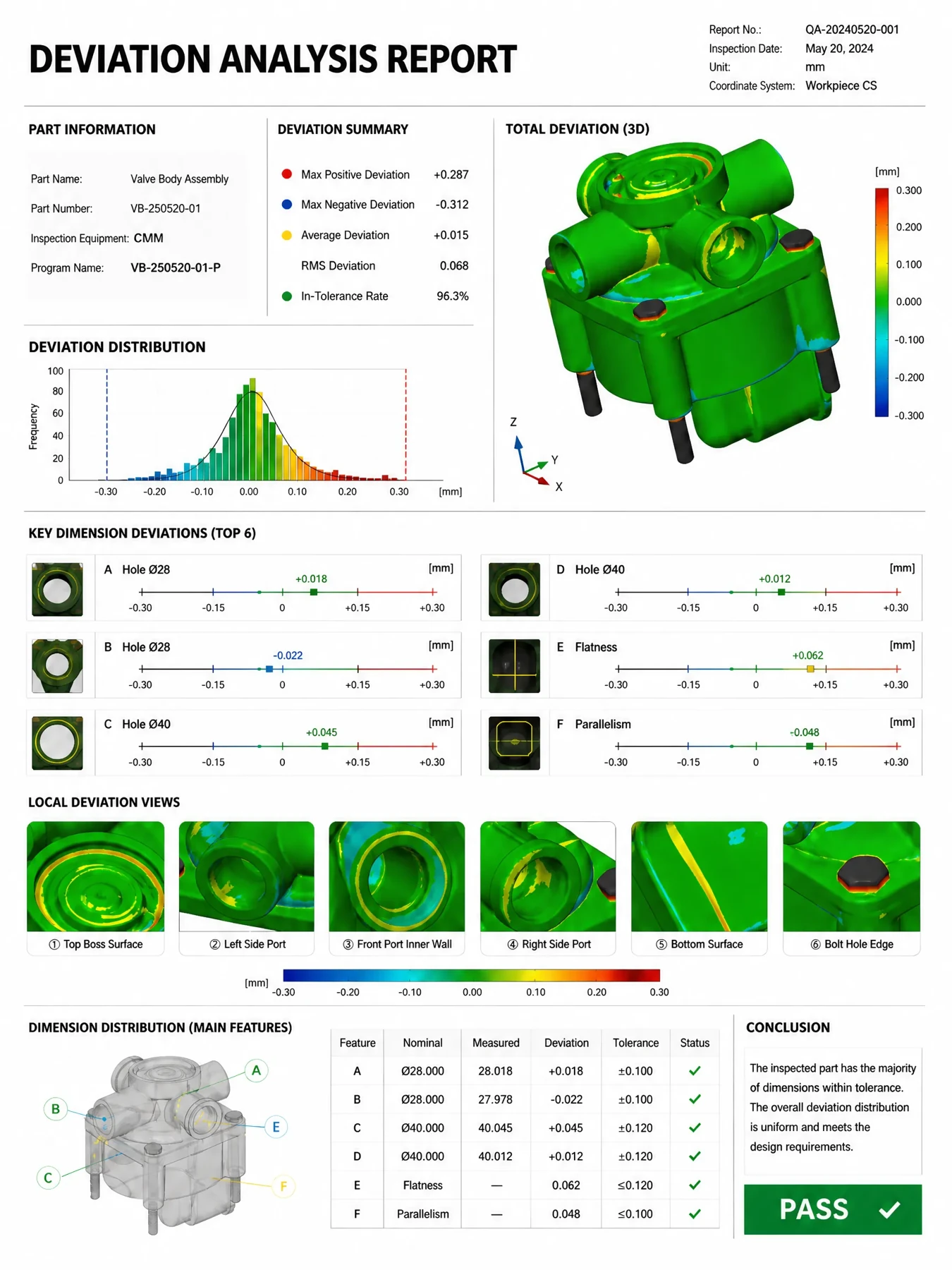
The results review links measured geometry with product requirements. The report documents the chosen alignment, inspected features and findings for further decisions.

Example measurement report with a colour deviation map
Example measurement report with a colour deviation map. Manufacturer demonstration.

EXAMPLE TASKS

What do you want to achieve?

01

Comparison with CAD

Comparing measured geometry with the design model.

02

Deformation and wear

Inspecting changes on sheet metal, tools and other components.

03

Documenting measurements

Preparing results for quality review and process improvement.

WORKFLOW / BASIS FOR CHOICE

Define the result.

The result is a measurement basis for decisions. The choice of system, alignment method and measurement process must suit the task's tolerances.

Enquiry checklist
  1. 01

    Defining requirements and references

    Define tolerances, reference CAD and inspected features.

  2. 02

    3D capture of the product

    Capture the part surface with a suitable measurement process.

  3. 03

    Alignment to reference geometry

    Choose the alignment based on the task's reference elements.

  4. 04

    Deviation analysis in metrology software

    Evaluate dimensions and deviations in metrology software.

  5. 05

    Results review and report

    Review the findings and document the result.

EXPLORE RELATED EQUIPMENT

Tools for your next step.

Full catalogue

3D ING / TALK ABOUT YOUR PROJECT

Show us the task.
Let's find the right solution.

WHAT TO INCLUDE IN YOUR ENQUIRY

Part dimensions and material, reference CAD, tolerances, inspected features and the desired scope of the report.

What do you want to scan and what result do you need?

Describe the object, its size, material and the intended use of the data. Together we can clarify the basis for choosing equipment.