
On-site measurement
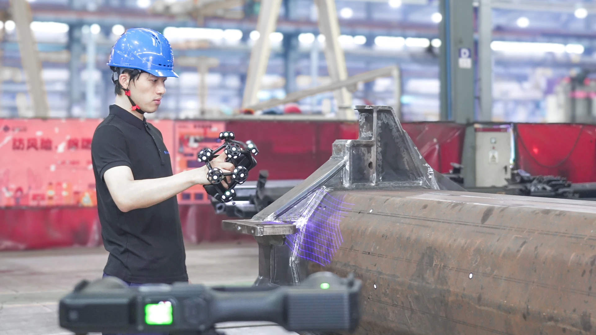
Capturing large parts and assemblies next to the production line.
01 / OVERVIEW
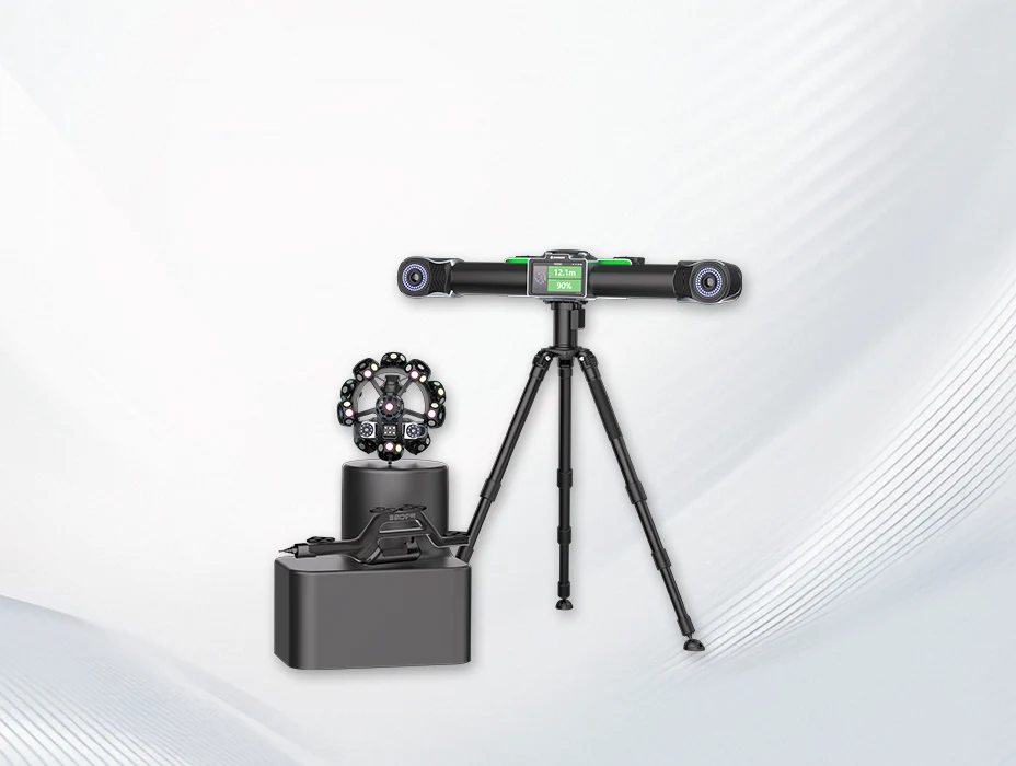
A wireless system for measurement in production and in the field. Use tracker and scanner together or separately; adapt the configuration to part size and surface access.
measuring configurations
Tracked scanning, standalone scanner or standalone tracker.tracking distance
GO-E version; GO-C has a tracking distance of 2.8 m.scanner weight
Without battery; tracker weight is 1,580 g without battery.02 / MOBILITY
The system packs into a single transport case. Wireless work and the option to connect an AirGO Pad make measuring large parts easier.
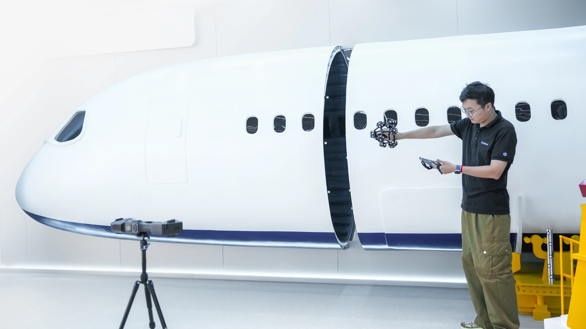
03 / FLEXIBILITY
Tracked mode enables marker-free capture. Using the scanner or tracker alone extends measuring options in different workspaces.
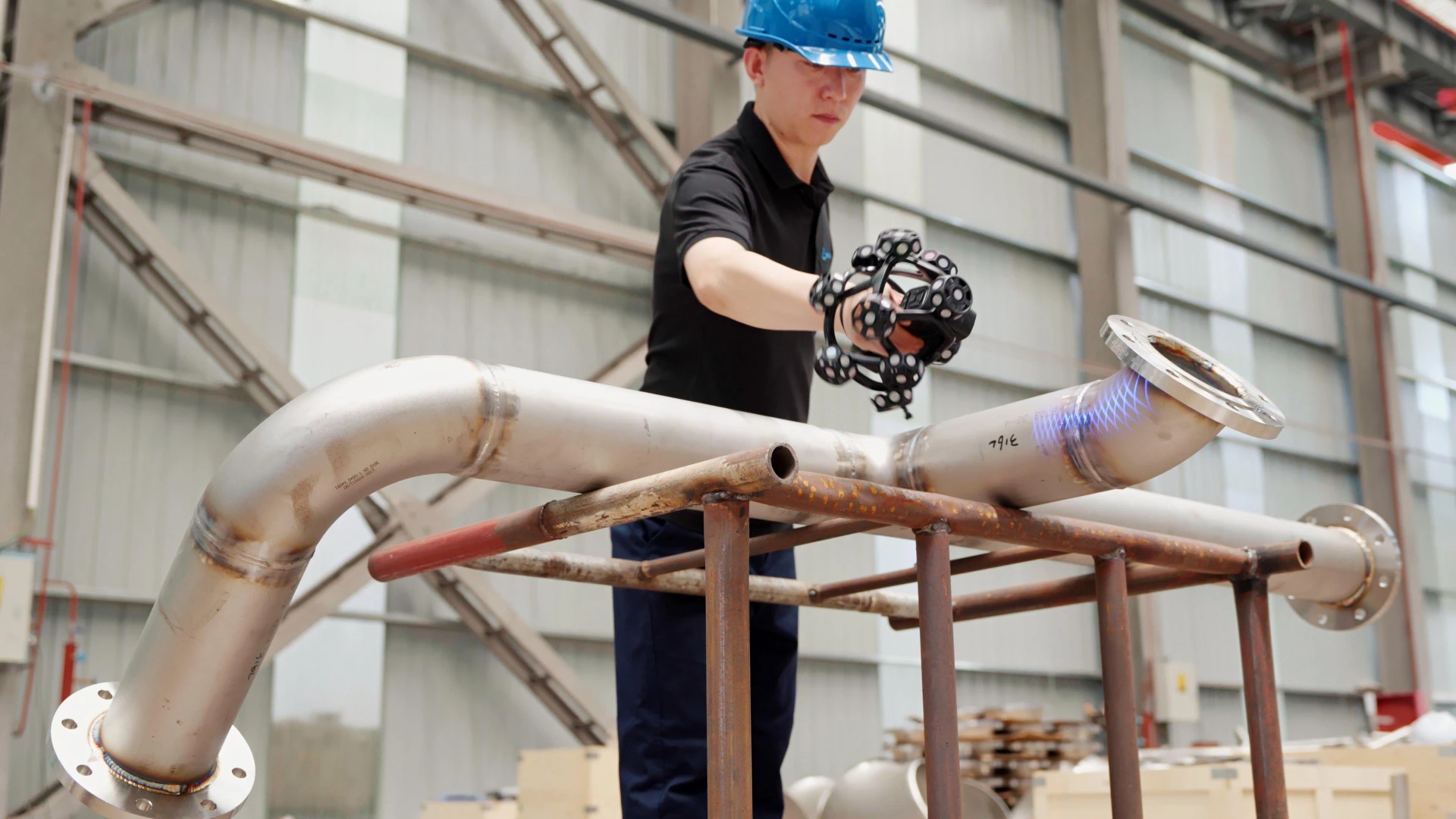
04 / COLOUR AND CONTEXT
A colour camera and AR overlay help compare the actual part with CAD. You can record scratches and dents on the model.
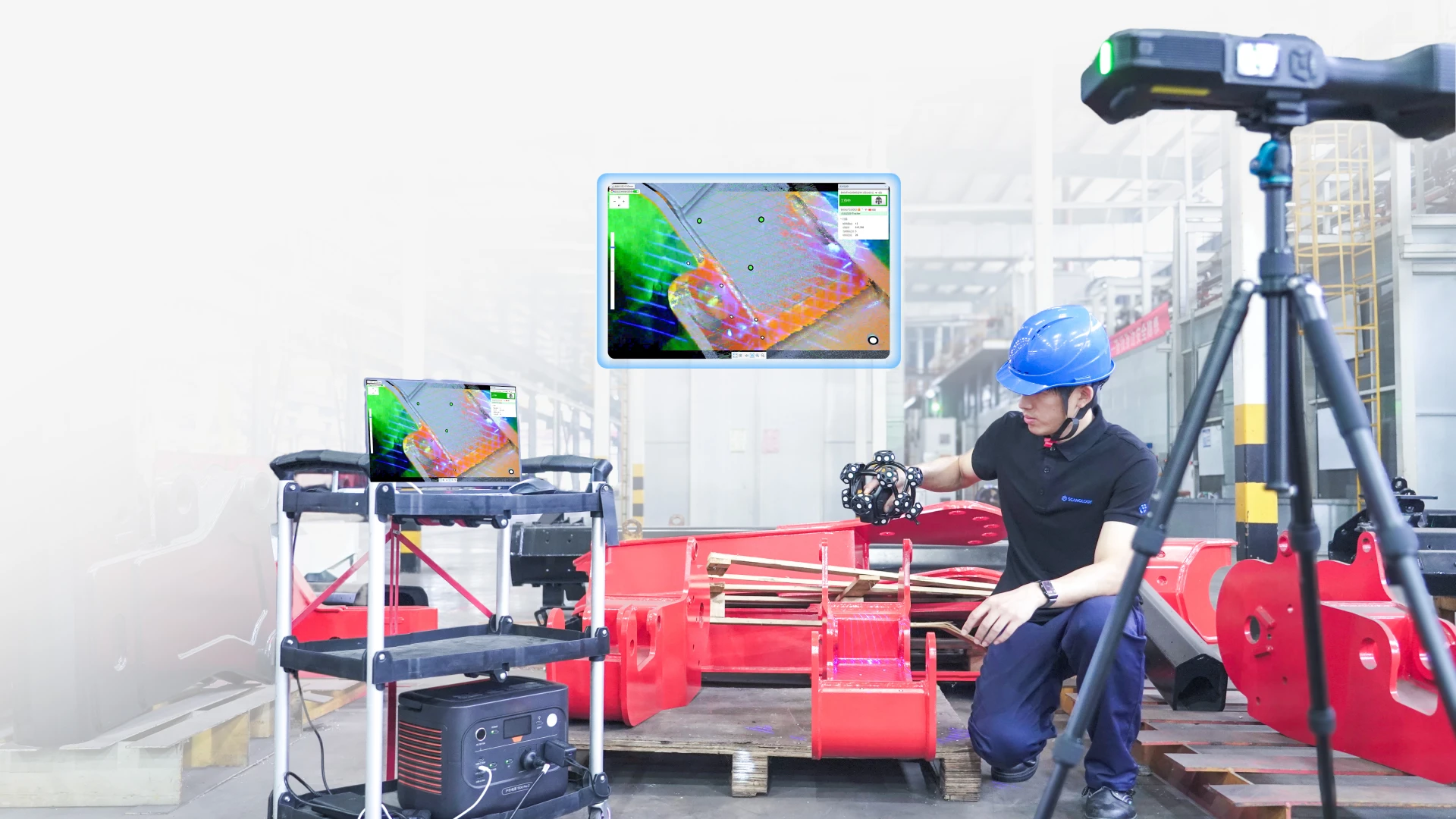
05 / CAPTURE MODES
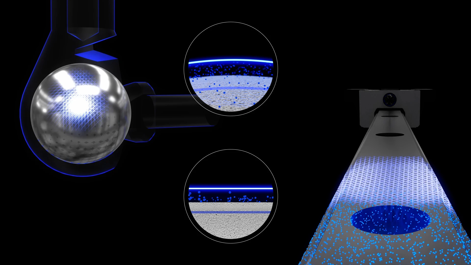
Fast, fine and deep-hole modes complement wide-area capture with the tracker. Choose the light pattern according to part geometry.
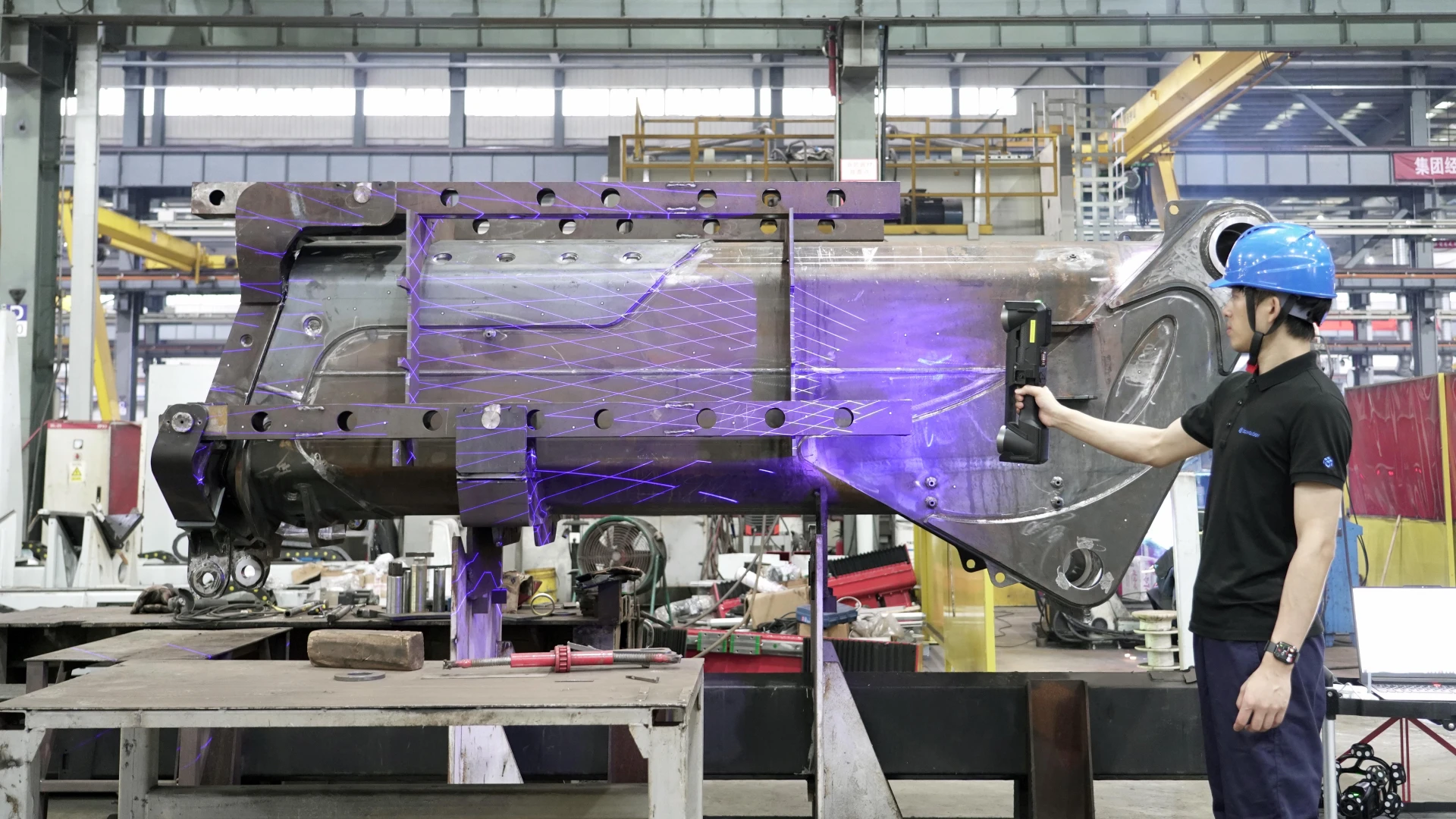
06 / CONTROLS
Displays on the scanner and tracker show information while you work. Configurable buttons give access to frequent tasks.
07 / MEASUREMENT RESULT
Measuring performance is also defined by volumetric accuracy, sphericity and flatness. When choosing, we consider the configuration and size of your part.
08 / FROM TASK TO RESULT
Capturing large parts and assemblies next to the production line.
Visual comparison of the actual part with CAD and recording surface defects.
Obtaining 3D geometry for further processing and reconstruction.
09 / TECHNICAL DATA
A selection of key parameters. When choosing, consider object size, required accuracy and working conditions.
Values apply to the stated mode and configuration. The manufacturer evaluates measurements per ISO 10360-13, VDI/VDE 2634-3 and JJF 1951 in its accredited laboratory. Accuracy, volumetric accuracy and resolution are different properties.
10 / RELATED EQUIPMENT
SCANOLOGY
Large parts. Accurate data.
Explore the product ↗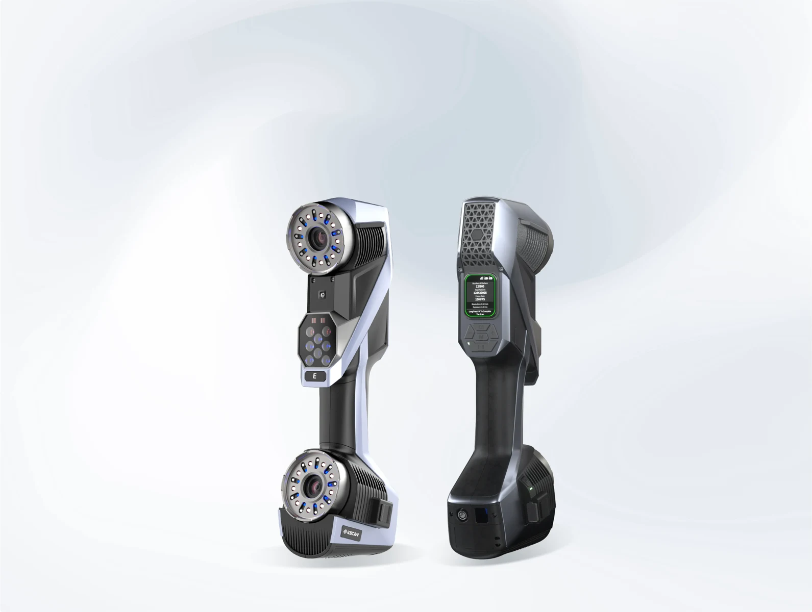
SCANOLOGY
From large parts to the finest details.
Explore the product ↗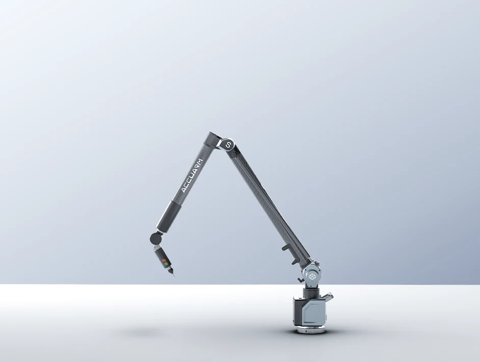
SCANOLOGY
Accurate contact measurement. Where you work.
Explore the product ↗3D ING / TALK ABOUT YOUR PROJECT
What do you want to scan and what result do you need?
Describe the object, its size, material and the intended use of the data. Together we can clarify the basis for choosing equipment.